Cloud Receiver Printer
Document Number: 3277 Revision Level: 1.6
The Cloud Receiver Printer is used by ASP Hosted and Disaster Recovery clients to view incoming signals. DICE will provide the necessary login credentials to access the printer. The printer receives and displays signals from Matrix, CORE, and (when applicable) outside automation software. This documentation defines the pages users can access within the printer to view and manage signaling information.
Users can access the Cloud Receiver Printer from a browser window. Upon logging in, users will have access to the available navigational headers and their options. These headers and their pages are defined below.
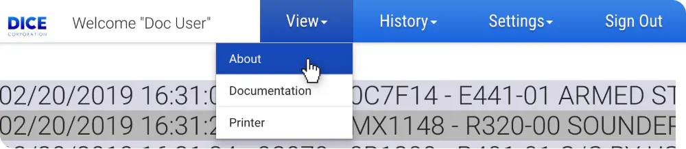
View
View provides access to the general printer information pages. These pages are defined below.
| Page | Description |
|---|---|
| About | Displays the Printer Server, Receiver Version, UL Listing Status, and the browser tested versions of Chrome, Firefox, Microsoft Edge, and Safari. |
| Documentation | Provides a downloadable copy of this instruction set. |
| Printer | A live feed of incoming signals received by the receivers. See the Printer section below for more information. |
History
History provides access to view and search signal records.

See the Receiver Signal Report section below for more information on interacting with signal history.
Settings
Settings provides access to view and manage line masking applied to DNISs.

See the Line Mask Settings section below for more information on how to manage line masking.
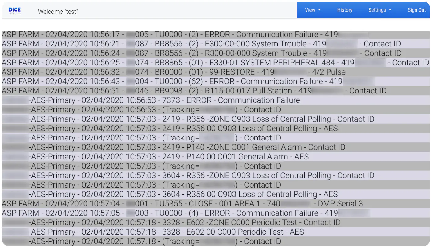
Printer
The printer is a live feed of incoming signals received by alarm receivers. The twenty (20) most recent signals are typically displayed. The printer will scroll as new signals are received.
From left to right, the printer displays the following information on each signal.
| Information | Description |
|---|---|
| Receiver | Displays the receiver that received the signal. |
| Date | The day, month, and year the signal was received. |
| Time | The local time the signal was received. |
| DNIS | The number dialed by the device that sent the signal. |
| Account Number | The account number that sent the signal. If custom line masking is configured, the masking will precede the account number. See the Line Mask Settings section for more information on how to manage line masking. |
| Signal Description | A brief explanation of the signal. |
| Caller ID | The phone number the panel used. |
| Signal Format | The alarm signal type communicated by the panel. |
Receiver Signal Report
The Receiver Signal Report allows users to view and filter received signal data. This page displays all signals received within the last 24 hours by default.
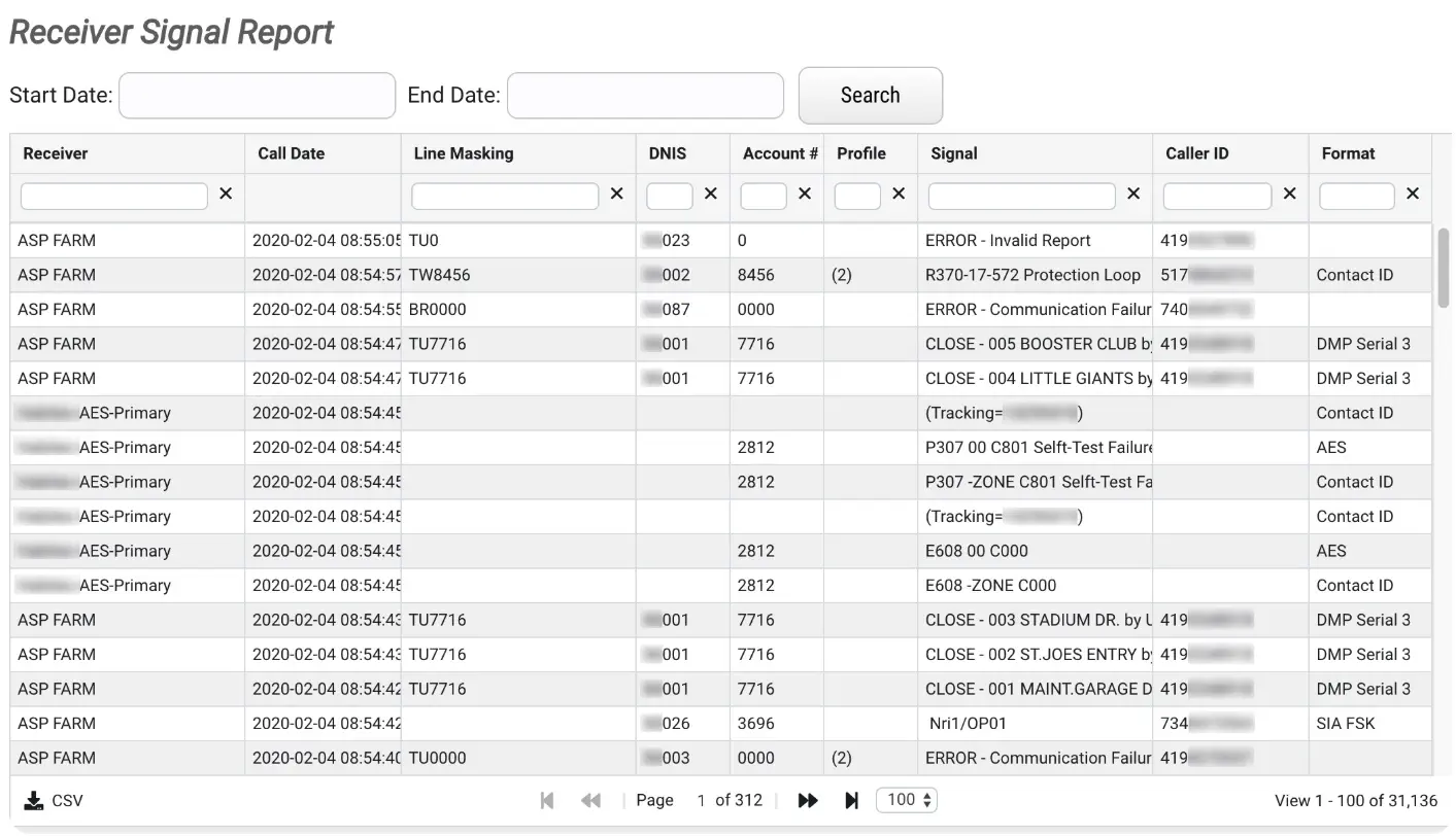
Users can interact with displayed signals via the available filtering and search options. These options are defined below.
Note: The Receiver column displays the name of the receiver that reported the signal. ASP FARM receivers report signals reported from any Telco lines going into the DICE ASP Receiver Farm. All other receivers will be your co-located receivers.
Start and End Dates
The Start and End date fields allow users to filter displayed signals by the date they were received.
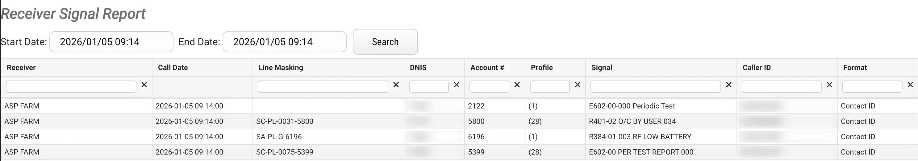
Perform the following steps to filter signals by date.
- Select the Start Date field to display the calendar and time options.
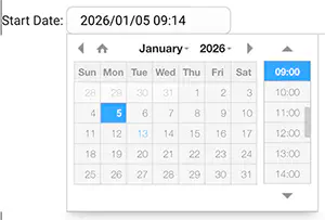
- Select the date and time the system should begin pulling signaling data.
- Select the End Date field to display the calendar and time options.
- Select the date and time the system should stop pulling signaling data.
- Select Search to populate the table with the results.
Column Search Fields
To refine a search further, use the available column search fields.

Multiple columns can be used simultaneously to refine with greater precision.
CSV
The CSV option allows users to download a copy of the table in CSV (Comma-Separated Values) format.
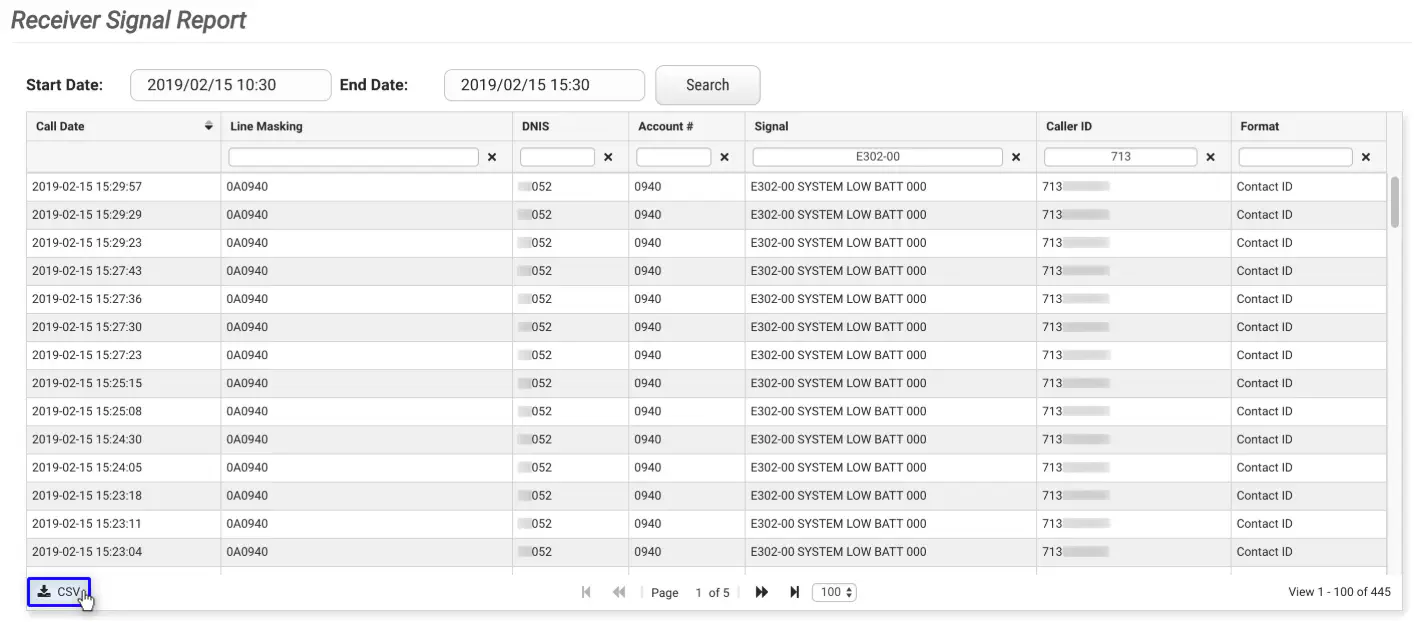
The downloaded file will contain the data within the currently viewed grid page only. If other pages of information are required, the user will have to toggle the grid to the desired page and select the CSV option. The timestamp on the file is converted from local time to UTC (Coordinated Universal Time).
Line Mask Settings
The Line Mask Settings page allows users to add additional identifiers to DNISs. Applying line masking is helpful to differentiate between panels.
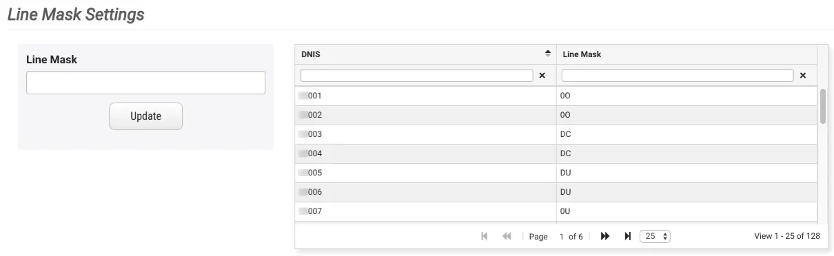
The client DNIS numbers and their existing line masks will display within the table. Users can select a DNIS to update or add line masking. Perform the following steps to add a line mask to a DNIS.
- Select the desired DNIS from the table.
- If the selected DNIS already has a line mask assigned to it, the Line Mask field will populate.
- Input a line mask in the Line Mask field (or update existing masking as needed).
- Note: Adding a dash after the line mask is recommended for easier readability.
- Select Update to apply the masking.
Once a new line mask has been applied, all signals incoming from the DNIS will display using the new mask.